Lab 2: ER Schema Design
In the previous lab, you informally described a database schema. In this lab, you will more formally describe a database schema by creating an Entity Relationship (ER) diagram.
Instructions
You are welcome to work with a partner. As usual, do not collaborate with students outside your group. If you have questions, please ask the instructors for help!
Design an ER schema for keeping track of information about votes taken in the U.S. House of Representatives during the current two-year congressional session. The database needs to keep track of each U.S. STATE’s Name (e.g., ‘Texas’, ‘New York’, ‘California’) and include the Region of the state (whose domain is {‘Northeast’, ‘Midwest’, ‘Southeast’, ‘Southwest’, ‘West’}). Each CONGRESS_PERSON in the House of Representatives is described by his or her Name, the STATE represented, the Start_date when the congressperson was first elected, and the political Party to which he or she belongs (whose domain is {‘Republican’, ‘Democrat’, ‘Independent’, ‘Other’}). The database keeps track of each BILL (i.e., proposed law), including the Bill_name, the Date_of_vote on the bill, whether the bill Passed_or_failed (whose domain is {‘Yes’, ‘No’}), and the Sponsor (the congressperson(s) who sponsored—that is, proposed—the bill). The database also keeps track of how each congressperson voted on each bill (domain of Vote attribute is {‘Yes’, ‘No’, ‘Abstain’, ‘Absent’}).
- Draw an ER schema diagram for the U.S. House of Representatives, capturing as many of the requirements described above as possible. Remember to include:
- Entities and their attributes
- Relationships and their attributes, if any
- Specify key attributes
- Specify relationship cardinality
- State any assumptions you make
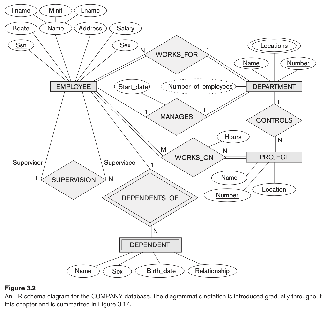
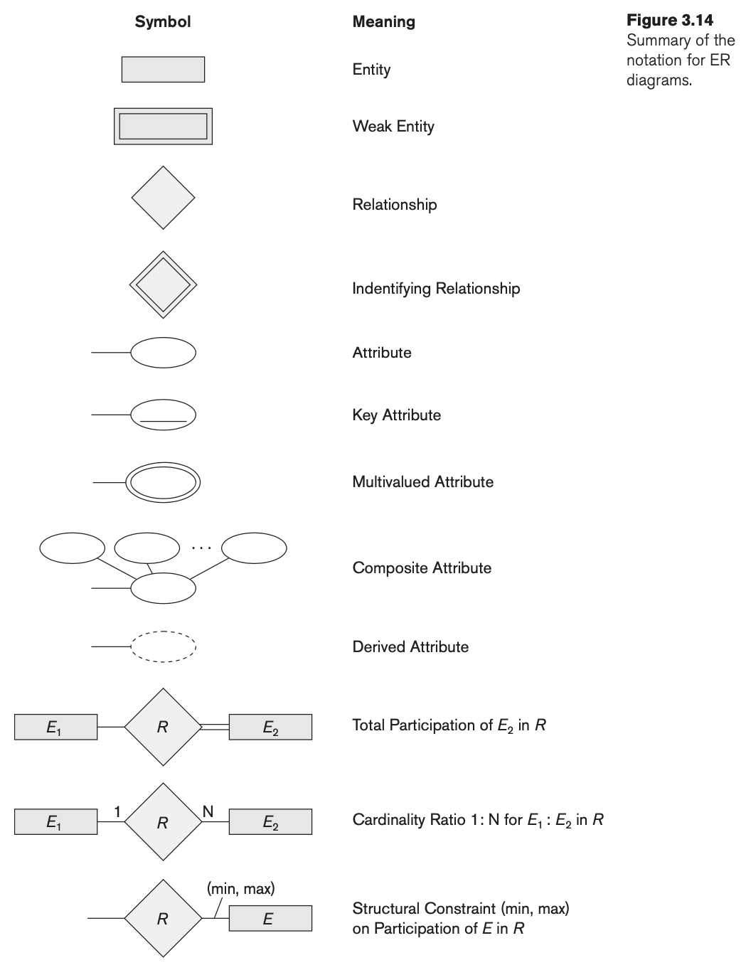
Figure 3.2 shows an example of an ER schema diagram. Figure 3.14 summarizes the notation used in ER schema diagrams. Try to use as much of the notation as makes sense.
Submit
Upload a PDF containing:
- A high-quality scan of your ER schema diagram
- An explanation of any assumptions you made
The assignment will be graded for accuracy and completeness, with some leniency for material we haven’t (yet) covered in lecture (e.g., weak entities).